Fantastic Flying Machines
Objective 1: You will design a fantasy flying machine based upon your research.
Objective 2: You will learn the fundamentals of orthographic projection & 1,2 and 3 pt perspective .
Objective 3: Fabricate your machine.
Objective 4: Your machine must fly. You will determine the velocity of your machine using v=d/t
Objective 2: You will learn the fundamentals of orthographic projection & 1,2 and 3 pt perspective .
Objective 3: Fabricate your machine.
Objective 4: Your machine must fly. You will determine the velocity of your machine using v=d/t
The History of Flight
Flight Basics
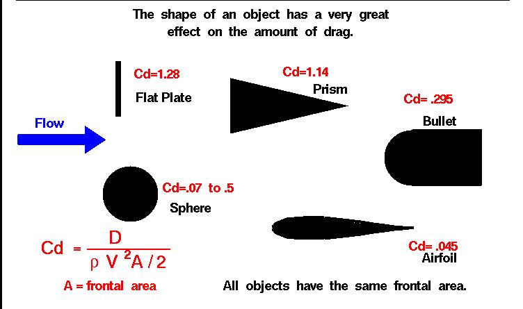
Drag Coefficient
|
How Does a Wing Actually Work?
|
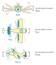
Movement Explanations
|
Vocabulary:
Linear Perspective-- a type of perspective used by artists in which the relative size, shape, and position of objects are determined by drawn or imagined lines converging at a point on the horizon. This can be done in 1,2,3,4 & 5 point perspective.
Vanishing Point-- the point at which receding parallel lines viewed in perspective appear to converge.
Horizon Line-- a horizontal line across the picture. It is always at eye level - its placement determines where we seem to be looking from - a high place, or from close to the ground.
Linear-- arranged in or extending along a straight or nearly straight line.
Parallel Lines-- two lines that are always the same distance apart and never touch.
Orthographic Drawing-- often called a "blueprint", is a way of representing a three-dimensional object in two dimensions. It uses different two-dimensional views of the object instead of a single three-dimensional view.
Aerodynamics-- the study of the properties of moving air, and especially of the interaction between the air and solid bodies moving through it. There are three basic forces to be considered in aerodynamics: Thrust--which moves an airplane forward Drag, which holds it back; and Lift, which keeps it airborne. Lift is generally explained by three theories:
Bernoulli's principle--says that if air speeds up the pressure is lowered. Thus a wing generates lift because the air goes faster over the top creating a region of low pressure, and thus lift.
Coanda Effect--the phenomena in which a jet flow attaches itself to a nearby surface and remains attached even when the surface curves away from the initial jet direction.
Newton's Third Law of Motion--each action brings an equal and opposite reaction. Forces are either pushes or pulls resulting from the interactions between objects.
Drag Coefficient--Drag is a force that acts parallel and in the same direction as the airflow. The drag coefficient of an object impacts the way the object passes through the surrounding air.
Velocity--is the speed of something in a given direction. v=distance traveled/time of travel (v=d/t)
Propeller--airfoil that spins rapidly, creating thrust which moves the airplane through the air.
Fuselage--holds the structure together and accommodate passengers and/or cargo.
Cockpit-- holds the pilot(s) and instrumentation.
Wing(s)--a form of airfoil, wings generate lift and control the airflow while flying. Wing design is a crucial factor in aviation: a wing is designed to reduce drag at the leading edge, generate lift by its crescent and manage airflow using the rear edge. Furthermore, while gliding (i.e. without engine power), the wings allow the pilot to increase and decrease the descent rate.
Flaps--Flaps adjust the camber of the wings, increasing lift. Flaps are normally fitted at the trailing edge of the wings.
Aileron--Ailerons increase or decrease lift asymmetrically, in order to change roll and, thus, move the aircraft left or right while flying. Ailerons are hinged sections fitted at the rear of each wing. Ailerons work asymmetrically as a pair: as the right aileron goes up, the left one comes down and vice versa, thus making the aircraft roll right or left, respectively.
Camber-- In aeronautics and aeronautical engineering, camber is the asymmetry between the top and the bottom surfaces of an airfoil(wing). An airfoil that is not cambered is called a symmetrical airfoil.
Horizontal Stabilizer--The horizontal stabilizer helps maintain an airplane's equilibrium and stability in flight. It does so by providing a mini wing at a certain distance from the main wings (typically at the back, although it can also be positioned at the from of the aircraft). This smaller wing produces enough lift to control the pitch of the aircraft and maintain its stability.
Vertical Stabilizer--The vertical stabiliser prevents lateral movements of the airplane. Without a vertical stabiliser, most aircraft would lose lateral control, tend to slip, increase drag and become uncontrollable.
Rudder--The rudder controls the yaw motion of an airplane. The rudder is a hinged surface fitted to the vertical stabiliser. When the rudder is turned to the left, the aircraft turns to the left in the horizontal plane; when the rudder is turned to the right, the aircraft turns to the right.
Pitch-- movement of the nose up or down about an axis running from wing to wing.
Yaw-- movement of the nose left or right about an axis running up and down.
Roll--rotation about an axis running from nose to tail.
Research for Designing a Flying Machine
Objective 1: Due March 28th, 2017
NO AIRSHIPS, BLIMPS OR HOT AIR BALLOONS (unless you have received prior permission)
- Watch the 2 videos & slideshow.
- Set up a Pinterest account using your school email & password.
- Pinterest Board: YourName_FlyingMachines1A
- Research: 19th c. flying machines, 20th c. airplanes-pre WWI, birds, the mechanics of flight, fish, marine mammals, Wright Brothers, Leonardo da Vinci flying machines, flying machine designs, Luigi Prina, Steampunk flying machines…
- Sketch 3 possible designs.
NO AIRSHIPS, BLIMPS OR HOT AIR BALLOONS (unless you have received prior permission)
Orthographic vs. Perspective Drawing
Objective 2:
First you will learn the rules of drawing with perspective & orthographic drawing. You will use this to render your fantastic machine as a "blueprint" in pencil. Now you will go over the previous drawing in pen to finish the image.
Requirements:
• Orthographic Drawing with a Front, Side & Top view of your machine.
• Orthographic Drawing with a Title Block consisiting of the name of the drawing, the person's name who prepared the drawing, class and period.
• Final Orthogaphic Drawing with extraneous marks such as unused construction lines erased & the finished work traced in black pen.
Focus is on including line, contrast/variety, balance, proportion, and unity.
•Self assessment & class critique
Materials:
Paper, ink pen, graphite
Orthographic Drawing: Designing Your Flying Machine
Due April 5th, 2017
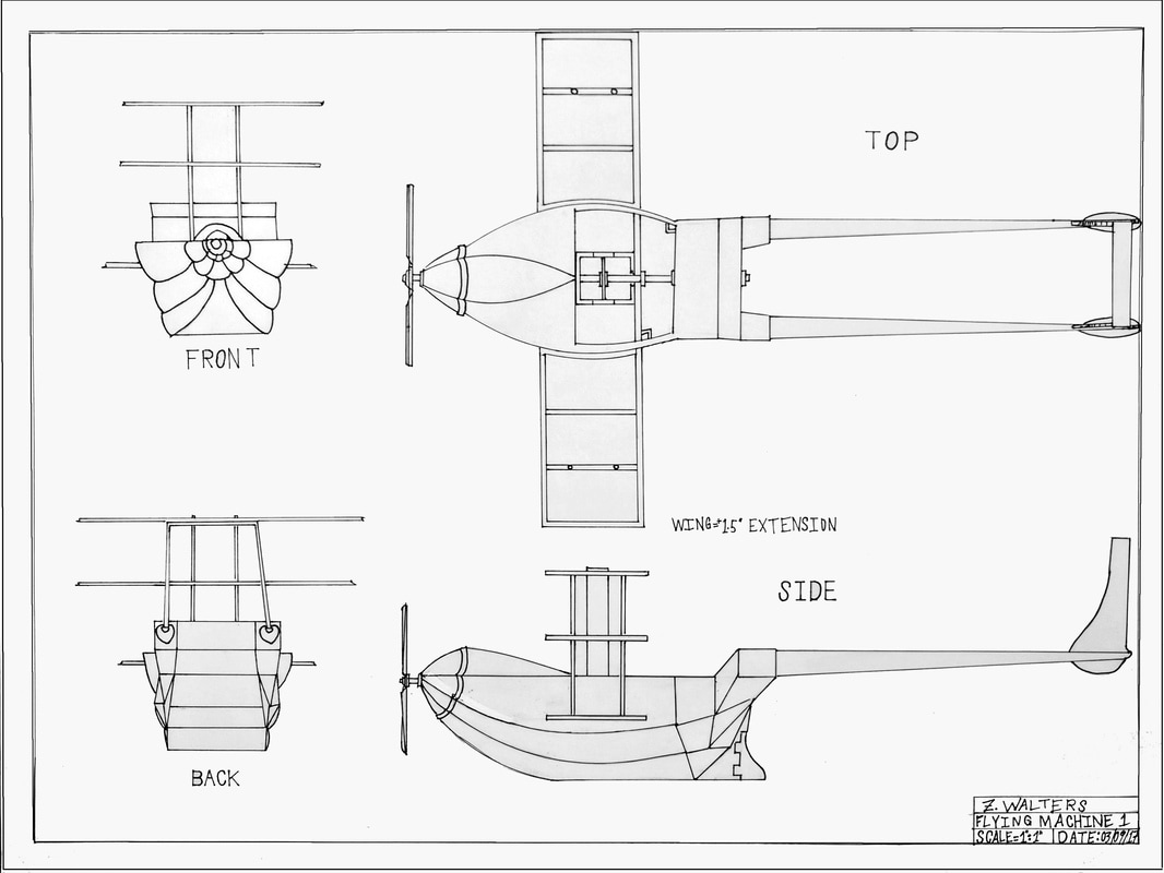
An Orthographic Projection/Drawing is often called a blueprint. We will not be concerned with a number of the rules that would govern a drawing for a detailed drafting class, but will recognize, prepare and be able to read a simple mechanical drawing.The best way to learn the parts and layout of a mechanical drawing is to create one with a pencil and paper. Follow the steps below,
Procedure:
1. Place the paper in landscape position, long dimension left and right.
2. Choose the front view first. Draw the FRONT VIEW IN THE TOP LEFT AREA OF THE PAPER. The Front View is our base view, with all other views aligned with the FRONT. Draw the Front View to scale using construction lines, object lines and making sure all lines are straight and neat.
3. Draw the BACK VIEW IN THE BOTTOM LEFT AREA OF THE PAPER.
4. Draw the TOP VIEW next to the FRONT View. Extend the construction lines for the front view up to the area of the Top View. The left side of the top view should exactly line up with the left side of the front view. This also applies to the right side. Finish the Top View.
5. Draw the SIDE VIEW to the right of the BACK View. Extend the construction lines of the top and bottom of the Front View to the right to the location of the Side View. Finish the Side View.
6. After the required views are complete, you will then add extension lines and dimension lines. A dimension line has arrowheads at the end that touch the extension lines or the object line. Dimension lines show the actual size of the object. The inch symbol " is usually omitted for this type of drawing. If needed, leader lines would be added to include additional information such as diameters of holes, radius of a curve or other important notes for fabrication.
7. You will then proceed to add a double border to the drawing using a thick solid line approx. 3/8 inches from the edge of the paper & at its edge.
You will add a title block to your drawing. This is typically in the lower right corner of the paper, touching the border line in this area. The Title Block will show the name of the drawing, the person's name who prepared the drawing, class and period.
8. To complete the drawing, any extraneous marks such as unused construction lines erased & the finished work traced in black pen.
Fabricating Your Flying Machine
Due May 18th, 2017
Objective 3: Fabrication
You will build your fantastic machine based upon your design.
Requirements:
• Your machine must look similar to your Orthographic Drawing. It is all right to change your design! Make note of any changes on your Orthographic Drawing.
•Self assessment & class critique
Materials:
Paper, railroad board, balsa wood, bamboo, glue, found objects
Objective 4: Flight & Velocity
• Your machine must be able to fly. Measure the distance and time of flight to determine its velocity. We will use cameras and a measuring tape to do this.
• Determine Velocity: v=distance traveled/time of travel (v=d/t)
• Self assessment & class critique
